This was a project that I began at the end of my freshman year of university. I saw a video by Aaed Musa, an engineering YouTube creator who made a video about a platform that can balance a steel ball bearing and decided that I wanted to replicate it. At the time I was taking linear algebra which ended up being really useful in understanding the Inverse Kinematics of the platform.
How it Works
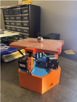
The platform operates using three Nema 17 Stepper motors that control heights of the three legs of the platform. Based on the height of the legs you can manipulate the pitch and roll of the platform. In order to determine how much the platform pitched and rolled I used a PID control loop to keep the ball balanced on the platform. The position of the ball was tracked using a resistive touch pad. These work by changing resistance depending on where pressure is being applied to the pad. You can then use a microcontroller to measure the voltage drop at the point where pressure is being applied and interpolate to find position. Once the position of the ball is known we define an error term in our control loop. The error is defined as the distance from the center of the platform. The goal of the PID Controller is to minimize the error or make it zero. When the error is zero, the ball is at the center of the platform.
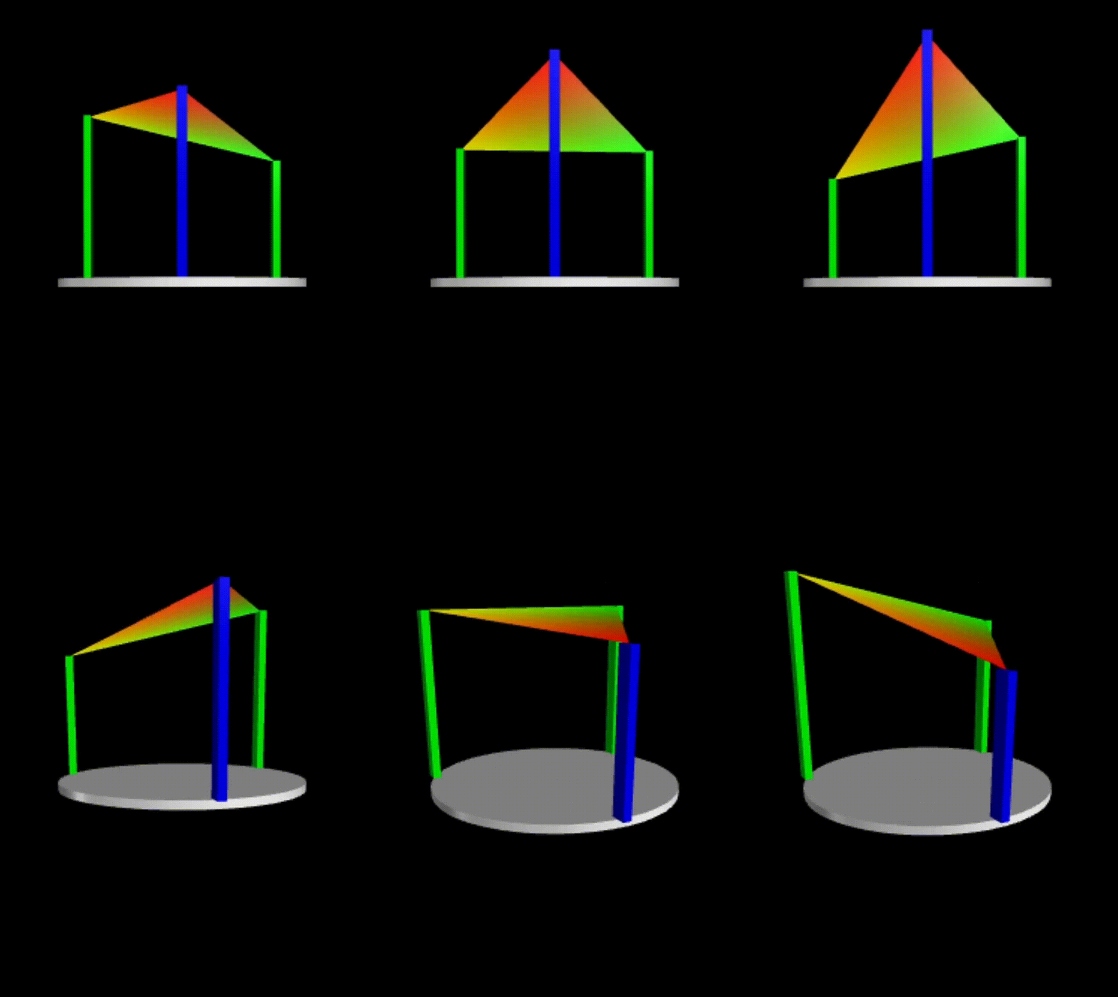
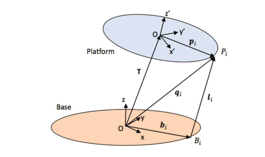
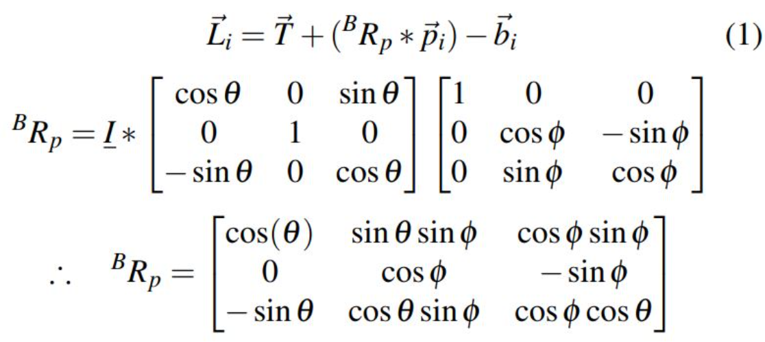
float s1[3], s2[3], s3[3];

float RotMatrix[3][3] = {
    {cos(theta), sin(theta)*sin(phi), cos(phi)*sin(theta)},
    {0.0, cos(phi), -sin(phi)},
    {-sin(theta), cos(theta) * sin(phi), cos(phi) * cos(theta)}
};

for (int i = 0; i < 3; i++) {
    float dotProduct_ba = 0.0;
    float dotProduct_bb = 0.0;
    float dotProduct_bc = 0.0;

    for (int j = 0; j < 3; j++) {
        dotProduct_ba += RotMatrix[i][j] * ba[j];
        dotProduct_bb += RotMatrix[i][j] * bb[j];
        dotProduct_bc += RotMatrix[i][j] * bc[j];
    }

    s1[i] = p[i] + dotProduct_ba - aa[i];
    s2[i] = p[i] + dotProduct_bb - ab[i];
    s3[i] = p[i] + dotProduct_bc - ac[i];
}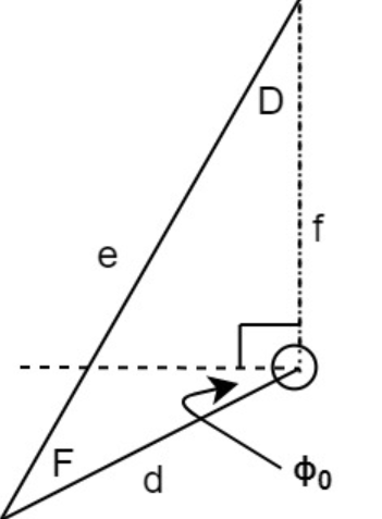
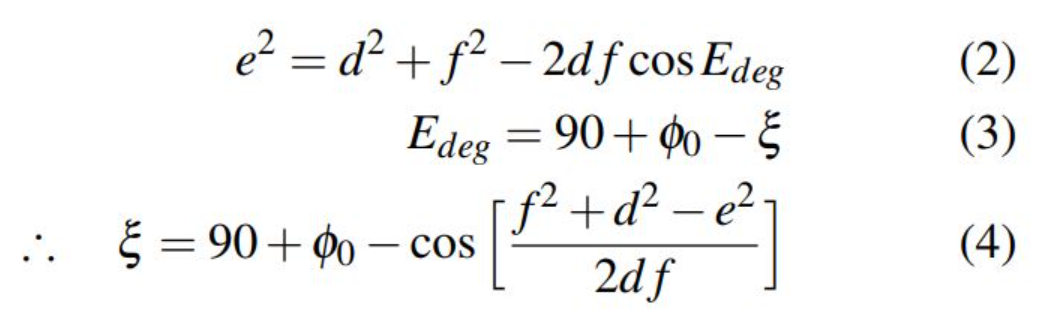
Since I was using stepper motors, I used two leg links to convert rotational translation into linear translation. This added an additional calculation where the angle of the stepper motor was determined using the law of cosines. The PID loop would give the desired distance to the ground, since this length, and the two link lengths were known, the motor angle was computed using the Law of Cosines. The equations used here are shown in figures 4 and 5.
float leg1 = sqrt(pow(s1[0], 2) + pow(s1[1], 2) + pow(s1[2], 2));
float leg2 = sqrt(pow(s2[0], 2) + pow(s2[1], 2) + pow(s2[2], 2));
float leg3 = sqrt(pow(s3[0], 2) + pow(s3[1], 2) + pow(s3[2], 2));

//motor angle 1
float numerator1 = pow(leg1, 2) + pow(joint1, 2) - pow(joint2, 2);
float denominator1 = 2 * leg1 * joint1;
motangle1 = acos(numerator1/denominator1);

//motor angle 2
float numerator2 = pow(leg2, 2) + pow(joint1, 2) - pow(joint2, 2);
float denominator2 = 2 * leg2 * joint1;
motangle2 = acos(numerator2/denominator2);

//motor angle 3
float numerator3 = pow(leg3, 2) + pow(joint1, 2) - pow(joint2, 2);
float denominator3 = 2 * leg3 * joint1;
motangle3 = acos(numerator3/denominator3);Electronics
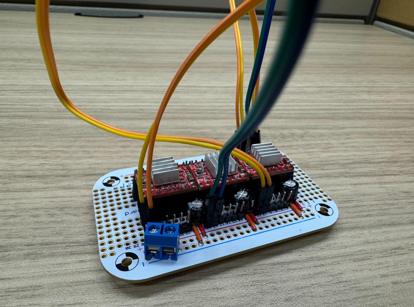
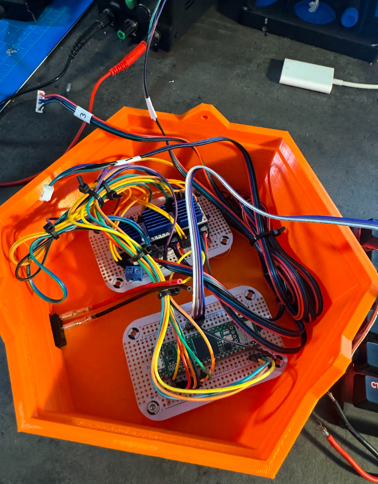
The electronics for the balancer are fairly minimal: a microcontroller, three stepper drivers, and the resistive touch pad. Each of the three Nema 17 motors is driven in step/direction mode, so every driver takes just two signal lines from the microcontroller, a pulse line and a direction line. A single enable line is shared across all three drivers so the motors can be released at once, and one more line selects the microstepping mode.
The drivers are configured for 1/16 microstepping, which turns the 1.8° full step of a Nema 17 into 3200 steps per revolution, or 0.1125° per step. This matters more than it might seem. Because the leg linkage converts motor rotation into leg height, the step size of the motor sets the smallest height change the platform can make, and therefore the smallest tilt correction it can apply. Microstepping gives the control loop fine enough resolution to make small corrections near the center of the platform, and it also keeps the motion quiet and smooth instead of stepping in visible jumps.
The three motors are commanded through the AccelStepper and MultiStepper libraries. MultiStepper is the important one here: it takes a target position for all three motors and runs them so that they arrive at the same time. If each motor were driven independently, the legs would finish moving at different moments and the platform would pass through tilt angles that the inverse kinematics never asked for, which shows up as a wobble that the control loop then has to fight.
The touch pad is a four-wire resistive touchscreen, read through four analog pins on the microcontroller. To find a position, one axis is driven as a voltage divider across the pad while the opposite pair of pins is used to measure the voltage at the point where the ball is pressing, and then the roles are swapped to read the other axis. That gives an X and Y reading for the ball, which is converted into a distance from the center of the platform and handed to the PID loop. When no pressure is detected at all, the pad reports no touch, so the firmware treats that as "no ball on the platform" and idles rather than reacting to noise.
The PID loop runs separately on the X and Y axes using gains of kp = 0.3, ki = 0.0005, and kd = 75, with an additional scaling factor that turns the size of the error into a stepper speed, so a ball far from the center is chased faster than one that has nearly settled. The derivative gain is large compared to the others because a ball rolling on a tilting plate has very little natural damping. The proportional term alone will happily push the ball past the center and set up an oscillation, so most of the work of settling the ball is done by reacting to how fast the error is changing rather than to the error itself. The integral gain is kept very small; it is there to clean up a steady offset from a platform that is not perfectly level, and anything larger tends to wind up while the ball is still in motion.