General Payload Teleop Device


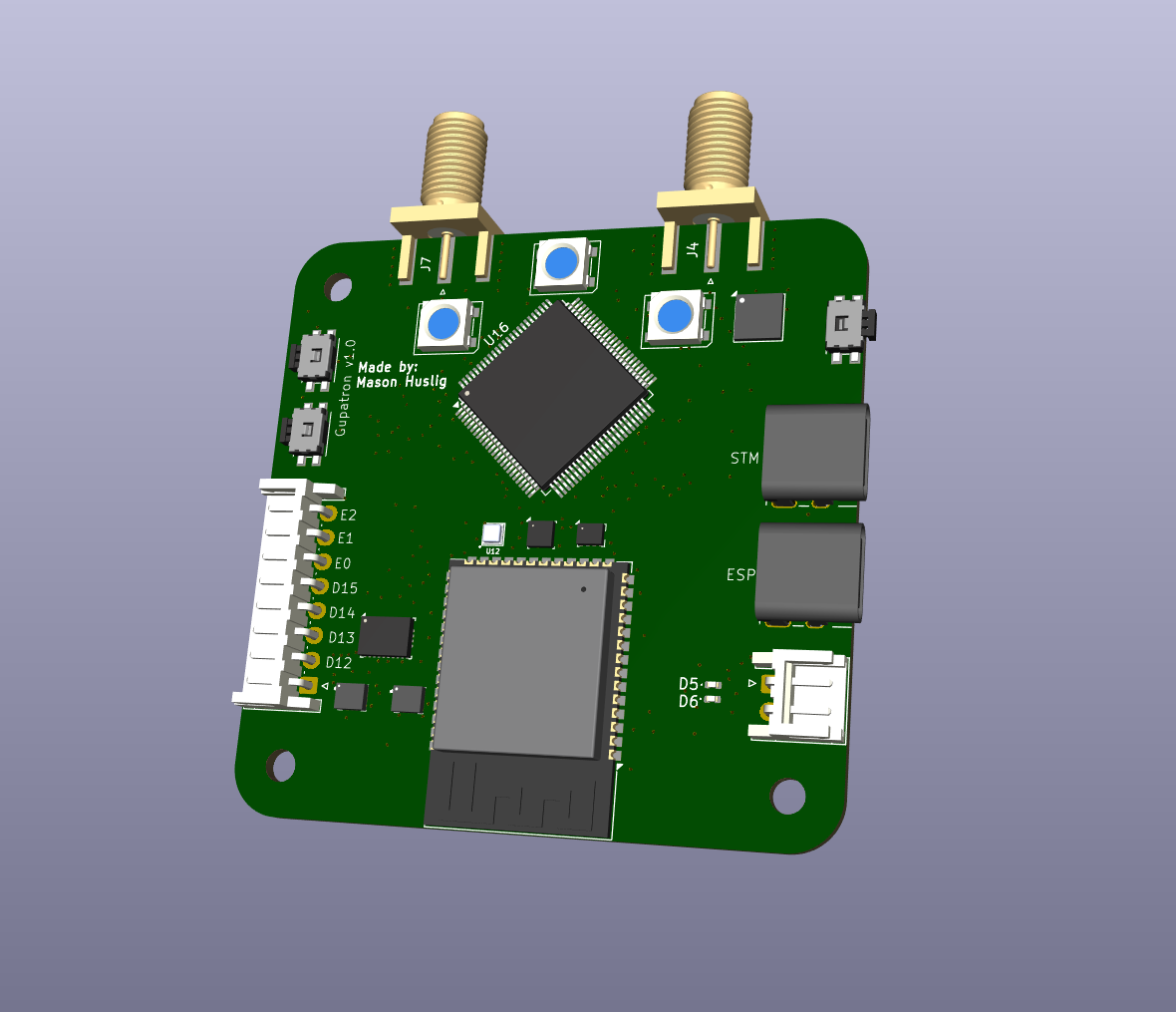
3D render of the assembled teleop board: a square green PCB labelled Gupatron v1.0 with two SMA antenna connectors, a large square microcontroller, an ESP32 module, two USB-C ports marked STM and ESP, several push buttons and a header broken out to pins D12 through E2
3D model of the board (Gupatron v1.0)
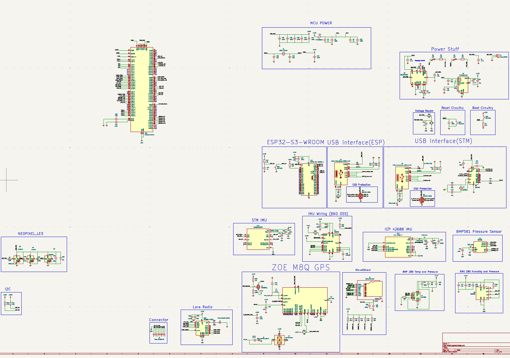
KiCad schematic for the payload teleop board: an STM32 microcontroller with MCU power, reset and boot circuitry, an ESP32-S3-WROOM co-processor, separate USB interfaces with ESD protection for each, a power section with charging circuit and regulators, a voltage reader, BNO055 / ICM-42688 / STM IMUs, BMP581, BMP280 and BME280 pressure and humidity sensors, a ZOE-M8Q GPS, a LoRa radio, a microSD card slot and a NeoPixel LED
Board schematic (click to open full size)
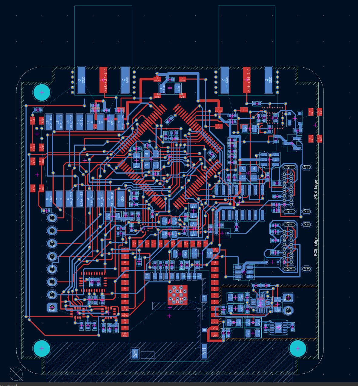
KiCad board layout of the payload teleop PCB, fully routed: red traces on the top copper layer and blue on the bottom, a large square microcontroller footprint at the centre, two antenna cutouts at the top, mounting holes at each rounded corner, broken-out pin headers down the left edge and the power section in the lower right
PCB layout, fully routed (click to open full size)