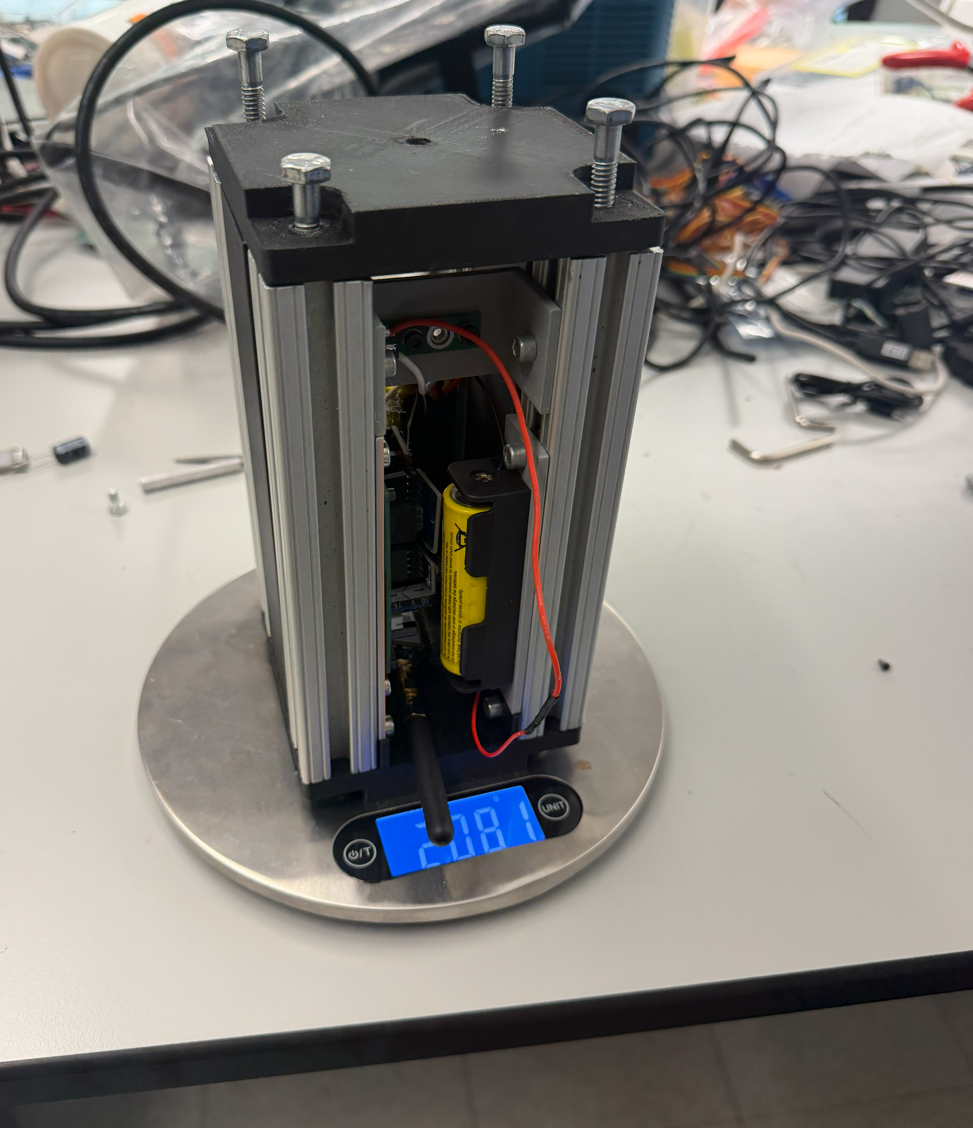
This project began at the start of the spring semester of my junior year of university. After a sudden change in leadership on the GW Rocket team, my friend needed someone to quickly step up and help design a payload that would be placed inside the rocket. The Payload needed to collect data like pressure, temperature, humidity as well as orientation of the rocket during launch. This data was to then be transmitted back to a ground station for live monitoring during the rocket's flight.
Constraints
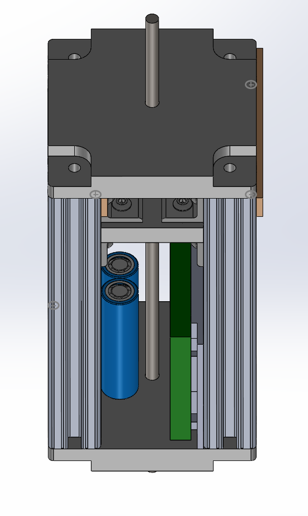
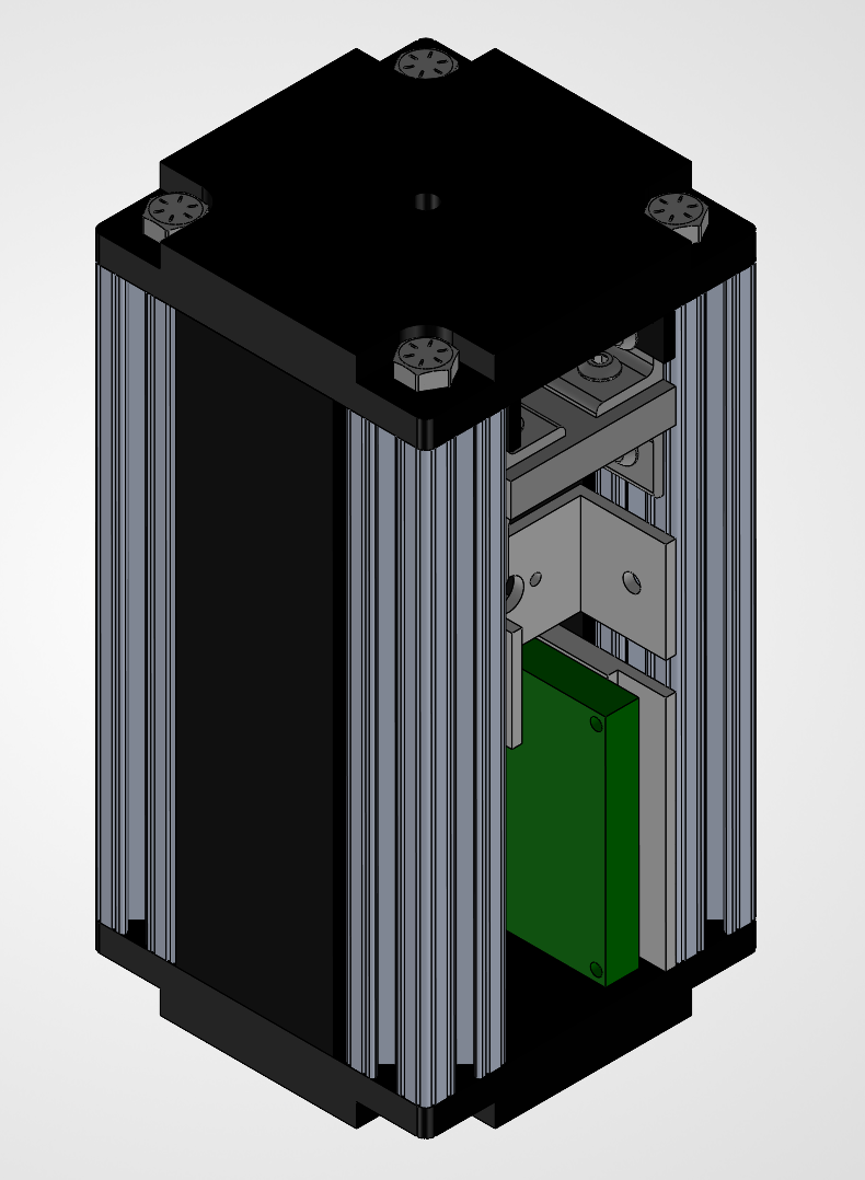
The Rocket Competition that the GWU rocket team competes in (IREC), places volume and weight constraints on each teams payload. This year, the payload was a non-deployable, 2U CubeSat form factor, which meant it had to fit a 100mm x 100mm x 200mm volume. Additionally, the total weight of the payload had to weigh no less than 2kg.
The biggest challenge as a team was fitting all the necessary electronic components, including the antenna on board the payload while still meeting the 2kg weight minimum which involved careful selection of materials to ensure that the weight limit was reached.
For supports we chose Aluminum extrusions. This was done for a number of reasons. The aluminum extrusions were heavy enough for our case and also allowed for an easy way to attach components like the electronics to the payload. Additionally, there was no concern that the aluminum extrusions would interfere with the antenna's performance as it is not ferromagnetic.
The aluminum extrusions were cut to size and holes were drilled and tapped to allow hardware to attch the lid of the payload on each side.
Electronics
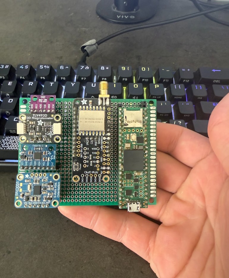
The electronics for the payload went through several different design iterations before the final electronic scheme was decided on. Initially, the circuit looked something like what is seen to the left. Pictured are two different IMU's the mpu 6050 and the BNO 055 to measure acceleration and orientation during flight. Assisting with orientation is a magnetometer which helps correct for drifting yaw over time as the rocket sits on the pad waiting to be launched. Lastly, we have a bme280 that measures barometric pressure, humidity and temperature. For the radio, I decided on a LoRa 915 MHz radio module. I chose this module because it did not require a license to operate and had found that others had used this chip in the past for amateur rocketry radio links. For the microcontroller I decided to use a Teensy 4.1. I chose this because there were some laying around the Lab, I was very familiar with them, and I also wanted to take advantage of the on board SD card. The SD card being a part of the microcontroller was also very important as I did not want any issues with data being corrupted during the launch itself. With the SD card, we could be sure that in case of radio link failure we could still recover data from the launch. This payload came along to the first test launch and although we did not launch there were some critical issue that I had discovered about the system. Firstly, the IMUs had been incorrectly mounted and made reading the orientation data from the rocket extremely difficult. Second, the Radio that I chose was extremely underpowered and had very low RSSI (Received Signal Strength Indicator) even at close distances which meant that I would not be able to maintain a reliable link to the rocket from far distances.
For the second iteration I decided to remove the magnetometer as it had very noisy measurements and actually made the yaw correction worse by constantly injecting noise into the filter. I also oriented the IMUs in the correct orientation so that reading and fusing their values would be much easier. Lastly, I moved away from the LoRa module and found some Digi XBee Radios laying around the GW Rocket shop. When I did some research on the radio I immediately found that outside of being a much more powerful radio, my favorite rocketry youtuber BPS Space had sworn by these radios for telemetry.
The Digi XBee radios have proprietary software (XCTU) that allowed for configuration and pairing of each radio which made the setup process much easier. Given the new radio setup and adequate time window between launches I saw the perfect opportunity to try and make a ground station antenna that would make the most of the XBee radios' capabilities.
Antenna
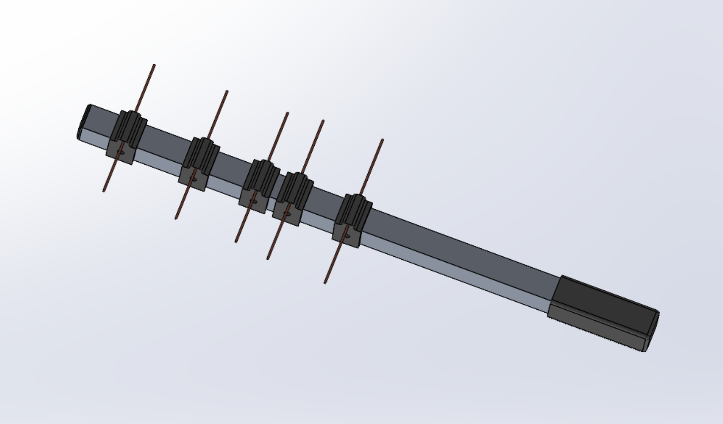
The Yagi antenna design was decided on so that we could get the most gain and directivity from the XBee radios as possible. Some antennas are directional, which means that you have to point them at your target transmitter in order to get the most gain out of them. For a Yagi antenna, the gain and directionality are determined by a few geometric factors of the antenna. The Yagi antenna has is made up of three different kinds of elements. Elements are the pieces that sit perpendicular to the antenna handle along the body of the antenna. You have the Reflector, Director, and Driven Element. The driven element is the one that is connected to a coax cable and then directly to your receiving radio. The Reflector element is the one that sits at the bottom of the antenna (closest to the handle). This element acts inductively and reflects energy back to the top of the antenna and suppresses radiation that would be coming from behind the person holding the antenna. Lastly, the Driven element which acts capacitively. These elements help focus the electromagnetic wave into a tighter, higher-gain beam.
When looking at a Yagi antenna, you will notice that the elements start widest at the bottom (closest to the handle) and taper like a christmas tree to smaller and smaller sizes. One key design consideration when making a Yagi Antenna is the number of driven elements that you use. Increasing the number of driven elements increases the gain but also narrows the "focus" of the antenna meaning that it is much more directional. Increasing the number of elements might make your RSSI much higher, but as soon as the rocket takes off the pad, it will be hard to follow with your antenna which could result in a drop in signal
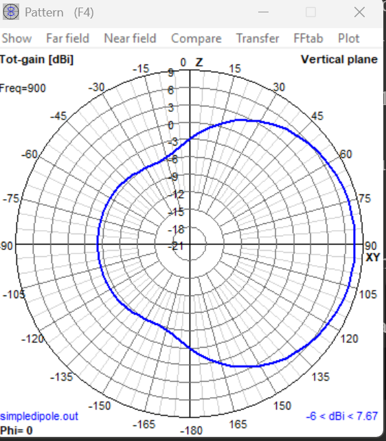
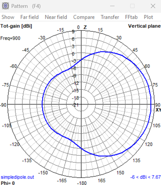
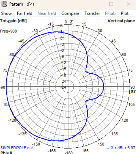
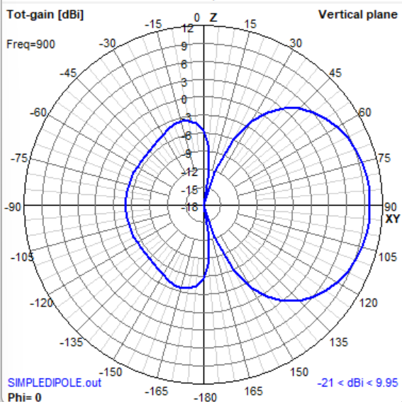
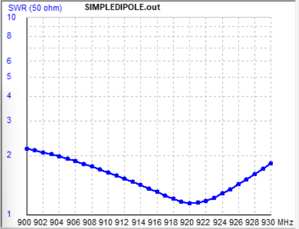
The directionality and gain are determined by the length and spacing between elements as well as how many you have. For this antenna, I learned how to use 4nec2 simulation software which gives you plots that characterize the antenna's Gain and Directionality, as well as how it performs at different frequencies. As can be pictured to the left, I went through multiple different design lengths for the elements and their spacing before I landed on a good radiation pattern and SWR plot. As can be seen, some of my intial attemps resulted in some atrocious radiation patterns (Figs 5 - 7) before I landed on something that looked good (Figure 8). The SWR plot tells you how much of the radios energy is reflected back to the radio at different frequencies. You want this number to be as close to one as possible at your desired transmitting frequency (A value of 1 meaning that none of the energy used to transmit is reflected back onto the radio). If you are uncareful, a high SWR could result in you frying your expensive radio :( as energy gets reflected back to the radio. In the SWR plot (Figure 9) you can see that the SWR is close to 1 at 920 MHz, which is what our radio was configured for in software.